Recently, one of our bioprocess engineers, Ellen, was presenting at the ISCCM 10 conference in Maastricht, NL. She was talking about a new “continuous” process we developed to produce quail muscle cells, you can watch the video here. This was able to generate 320 g of yield from an 800 mL vessel. Ellen’s key points were:
- Sustainable - we can run it for a long time
- Scalable - produces high yield even from small reactors
- Efficient - we used automation to reduce waste
From a technical side, this process required the integration of several different systems. In this article I will explain how we got this done rapidly and cost effectively.
Overview #
The impetus for this process came from the team testing out an online biomass measurement probe from Aber. This is a sensitive electronic probe that records the capacitance and conductivity of the liquid around it. Each cell has a small capacitative capability, as it is an enclosed, insulated capsule that can store charge. So, by measuring capacitance of the cell growth medium, you can get a proxy for cell density and therefore biomass.
The plan for this process was to run a bioreactor, and continuously feed and harvest the reactor, all powered by real-time measurements of biomass and total vessel mass. Media is fed in to keep the vessel mass constant, and media is harvested when the cell density goes above the target. This keeps the cells growing at optimal speed, whilst continuously harvesting biomass (product) and topping up the vessel with fresh media.
Ellen and team came to the me with the idea, and it was my task to make a working system.
Planning #
Previously when we had been looking to create a system that could control a pump to maintain a desired setpoint of vessel mass, I had looked at several off-the-shelf options. Someone in a nearby lab had a masterflex pump setup with a system that used a specific combination of pump, scale and software running on a windows tablet to achieve the goal. Systems like this can cost several thousand. I quickly realised that we would need to build something ourselves in order to meet the cost and speed requirements.
Analogue or Digital? #
Most of the pump suppliers for lab and process pumps offer only analogue control with 4-20 mA or 0-10 V DC, whereas most of the scales supply a digital output. I made a quick plan for a system that would use a microcontroller with an additional Digital to Analog Converter (DAC) in order to send the control signal to the pump. I had already ruled out PLCs as they are expensive, require supporting hardware and provide limited programming flexibility.
However I still had a bad feeling about this. Sending out an analogue signal would mean that the controller would not actually know the rpm of the pump; it just seemed a bit archaic to me. I was already disenfranchised with the world of OT (as you will see in other articles).
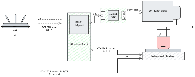
So instead, I did some digging around and found a peristaltic pump that can be controlled digitally. Even better, because these pumps were super affordable, cheaper than the analogue-only ones. They have an RS485 interface, which is very hardy and simple, and use Modbus on the application layer. Combine a custom-soldered cable with a USB-RS485 adapter from Amazon and you have a peristaltic pump you can control over USB for less than £4001.
Software #
To create the software to run this process I decided to completely revamp and expand on my previous pump control software, which was only capable of controlling one pump, based on one scale reading. I decided to put in the extra effort to create a fully generalised, modular controller, where you can define any input, control algorithm and output you want2. This took the majority of the time, however the extra effort was worth it to have a future-proof system.
With this new modular software done, we could build our system.
The System #
Here is a little diagram of the system:
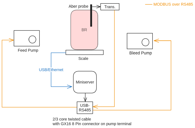
Armed with my new modular controller, I created input and output configurations for the Aber probe, scale and pumps. This system is relatively simple, there are two control loops, where a control loop is defined as the following:
- Input signal
- Control algorithm - maps input to output,
- Output actuator
So for the harvest line, the input was the Aber probe capacitance reading, the controller was a PID algorithm, and the output actuator was the harvest line pump that removes media from the reactor and into a harvest bag.
The software runs on a typical “mini pc” that you can get online, with Debian as the OS. It is running on a UPS for backup power supply. Even low end modern CPUs are capable of doing billions of operations per second, so can be theoretically faster than an average PLC. In our experience, they are also perfectly reliable to run for months with no intervention3. We use modern IT infrastructure monitoring software like Netdata to monitor the health of all of our control nodes. Another advantage of using a PC over a PLC is that I can ssh into the pc from anywhere and fix anything that might come up.
After some experimentation to get the right PID tunings and ironing out some bugs, we were ready to roll.
Behaviour #
We were initially a bit worried how well a PID controller would be able to control the cell density. We had no idea if the capacitance would respond nicely to increased harvesting, or if it would provide a closed-enough system for the control loop to function. Fortunately, all of our worry was for naught. As you can see in the figure below, the capacitance tracks really nicely to the setpoint of the controller.
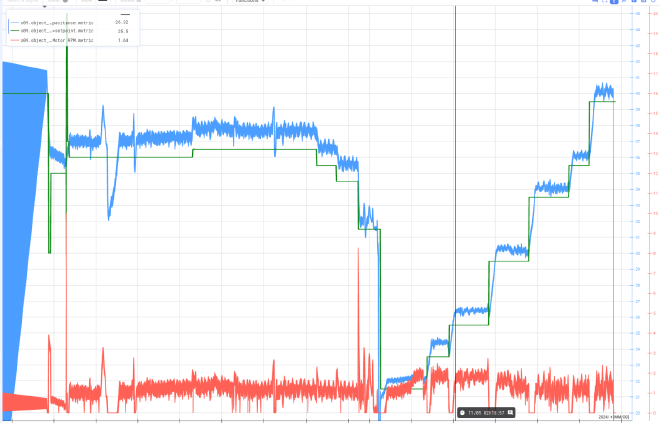
During the latter phase of the process, the process engineers needed to perform a large harvest to “save” the culture; the metabolites were out of whack. Afterwards, you can see that the cell density (measured by capacitance) picks up really nicely and holds at each of the setpoint levels as it is slowly bumped up. At the end, the team decided to just push it to see how high it could go. You can see that when the pump was not active, the cells begin to grow at a rapid rate, and then they become limited by the setpoint as the pump activates and begins to harvest. This allowed the engineers to keep the cells growing in an exponential phase, and gradually produce more and more cells.
We didn’t even have to worry about keeping enough media in the reactor, as the pump control loop was handling that for us. Whenever we harvested more, the feed pump would just top up the reactor to the desired level.
This provided a really nice interface for the bioprocess engineers, who now didn’t have to worry about carefully manually balancing the feed and harvest lines. Instead, they could just look at the metabolites, use their expertise to judge the health of the process, and set a suitable cell density setpoint to aim for. The system would then make it so.
Enablers #
How did we get this done so fast and for less than £1500?4
The reason we could achieve this comes down to a few things:
- We have the right in-house skills
- The equipment was using open standards such as Modbus RTU and RS485.
- We chose helpful suppliers who are willing to provide documentation.
We’ve had a really mixed experience with our equipment suppliers. Some of them will go to every length to help you, whereas others just want to charge you a service fee. Aber in particular was very helpful in providing documentation for their modbus interface, as was Kamoer, the pump supplier. For some suppliers, providing documentation for the digital interfaces on their own product seems to be a novel concept.
I would also like to stress that “open standards” means that it is a well known standard, and documentation and software libraries can be found online with open-source licences.
Having the right skills is probably the most influential factor however. There are now so many students graduating from Computer Science degrees, they cannot all get jobs in software. Go hire one. Biotech companies work with data and computer systems on a daily basis, and the biologists have enough work to do. Importantly; if you have someone who has the skills or the potential to become a tech specialist, give them the space and backing to grow into one.
Further plans #
We are already working on extending this modular control platform into a unified control layer. Such a system will allow our process engineers to interact with all of our reactors and equipment in a “single pane of glass” that can be viewed anywhere on any device.
This empowers us to keep expanding our production capacity, with reduced overhead spending for vendor-specific control systems. Also, laying the foundations for building our own custom hardware. There are exciting times ahead!
-
We aren’t trying to be cheap, the main issue facing cultivated meat is to get to price parity. The cost of all of the manufacturing ends up in the price of the product, so having cost effective operations is crucial. ↩︎
-
This was initially implemented in python, however I am working on a v3 that will be in Golang. Python not having strong typing, strict error handling or first-class concurrency really caused me a lot of headaches. My opinion is that python is a scripting language, not an application language. ↩︎
-
As long as you aren’t using windows. ↩︎
-
Scale, pumps, adaptors and control PC included in this figure. Aber probe and bioreactor system not included. ↩︎